The
Studio C Control System manages all elements of the animatronic show at Chuck E Cheese locations featuring the
Studio C show type, in addition to controlling some ancillary equipment such as the Karaoke system (during the period in which it was being used).
This system is a major technological departure from the previous show control systems used by the chain, marking a move to using more standard hardware and protocols. It is also the first Chuck E Cheese control system able to seek to arbitrary, frame-addressable locations on the accompanying video.
It is believed that this system is an evolution of a control system originally designed for the
Awesome Adventure Machine show.
Some Studio C documentation includes references to the video system of the Studio C Interactive Console used at
Studio C Alpha locations. The video portion of the Interactive Console system is not discussed on this page as it has no direct connections to the rest of the show video control system.
Laserdiscs were used for audio and video storage in the earliest deployments of this system. All deployments later moved to the DVD format. The term 'VDP' will be used to refer to players of either of these formats interchangeably, as the type of media makes no significant difference to the architecture of the system.
Show Computer
The
Show Computer manages all functions of the show. It is comprised of a standard x86 PC running an unknown variant of DOS and the
Cyberstar 2000 software, with a few additional hardware components including a custom ISA card. The user interface is controlled through an integrated display on the computer's front panel, and a keyboard on a rack shelf. Show data and software updates are loaded through a 3.5' 1.44MB floppy disk drive. This data is copied to and run from internal storage, using a Maxtor 3.5 Series DiamondMax Plus 8 40GB ATA/133 HDD.
Expansion cards
- Modem - Connected to a telephone line, along with the phone in the rack. Used during the laserdisc show era to download the control data, believed to be unused currently.
- Transmitter Card - Primary external show control interface. Handles all character valve control and some ancillary functions. Discussed in additional detail its own section below.
- 8-port RS-232 Serial Card - Interfaces with additional external show hardware. This is broken out to eight DB-25 connectors, which lead to the following components:
- Manager Terminal
- A/V switcher
- VDP 1
- VDP 2
- VDP 3
- Unused
- Karaoke controller
- Fire alarm system (in some locations)
Transmitter Card
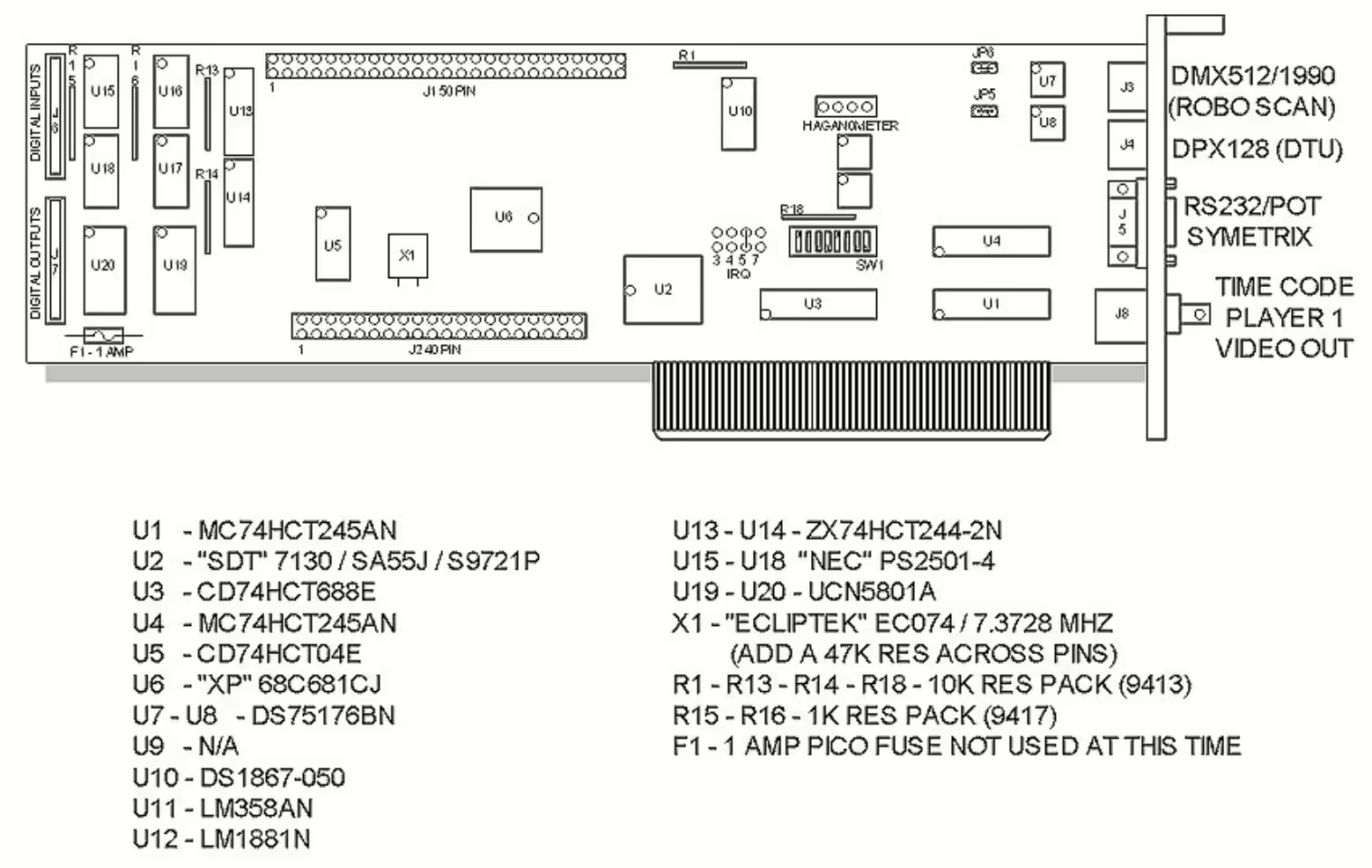
A custom ISA card in the Show Computer known as the
Transmitter Card handles all control of animation and lighting for the show, and provides the output to the SPL computer or COP Controller (depending on location type) for show volume adjustment. Two mini-DIN connectors provide DMX512 output for show lighting and DPX128 (custom protocol on top of RS-485) for communication to the COP Controller and DTUs, while RS-232 data and a digital simulated potentiometer is output via a DE-9 for volume control. A BNC connector accepts video input from the black burst generator for use as a control timing reference and will trigger a selectable IRQ.
The Transmitter Card is its own self-contained computer system based around a CPU Card. Communication between the card's CPU and the host PC is through 1KB of shared memory. This memory is dual-port and can be read or written by either side at any time.
The 'Transmitter Card' name comes from the store technician documentation. Internally, the Cyberstar 2000 software refers to this card as 'DPC50'.
DTUs
The Studio C system contains two
DTUs, used to control air valves on the characters and solid-state relays for lighting. Each DTU is based around a CPU Card and provides 64 open-collector digital output channels, with on-board LEDs showing the status of each channel. A
Studio C Tech Term can be connected to a DTU for diagnostic and troubleshooting purposes. The Tech Term connectors on both DTUs are typically wired out to a keystone wall plate for easier access when working on the show.
'DTU' Stands for Digital Terminal Unit.
CPU Card
The
CPU Card is a standardized 68HC11-based microcontroller module used in several Studio C systems. The module itself is a generic design, and a socketed EPROM contains the program specific for the hardware in which it is installed. It connects to the host system through two large pin headers which presumably expose most of the system bus. An on-board RS-232 port is available via a modular connector.
| MCU |
MC68HC11F1CFN4 @ 16MHz |
|
| ROM |
Socketed 27C256 EPROM |
AT27C256R OTP variant apparently used |
| RAM |
1KByte |
Internal to MCU |
| EEPROM |
512 bytes |
Internal to MCU |
| Interfaces |
RS-232, raw system bus |
|
The CPU Card is used in the Transmitter Card, COP Controller, and DTUs.
Early versions of the module require manually jumper pins 2-3 on JP6 for use in a COP Controller. This jumper can be left in place for use in other hardware. The jumper's actual function is unknown.
Manager Terminal
The
Manager Terminal is an off-the-shelf Beijer Electronics QTERM-K65 series terminal and is the primary interface for controlling the animatronic show. Located on a wall in the manager's office, it allows the show to be started and stopped, birthday names entered, and other administrative functions such as show volume adjustment. As this is essentially a 'dumb' terminal, it is driven by software on the Show Computer via a 57600-baud 8-N-1 RS-232 serial link. The panel on which the Manager Terminal is mounted also holds a microphone for paging and announcement purposes, connected back to the rest of the show's audio system.
COP Controller
The
COP Controller is responsible for additional processing of show audio and video, in addition to control of the Scan Cam on equipped locations. An alternate hardware version known as the COP Controller II adds volume control functionality and is used in Small Town locations as they lack the SPL computer normally used for volume control. It is presently unknown what the 'COP' acronym stands for.
More information on the COP Controller's A/V processing functions can be found in the A/V system section of this page.
A/V system
The Studio C
A/V system features several video monitors and speakers throughout the restaurant. The
A/V switcher, a Sigma Series 2100 frame containing several modules, handles all audio and video routing. It receives audio and video input from the VDPs and can route the content to the appropriate output devices, and the routing is controlled by the Show Computer via a 9600-baud RS-232 serial link. The
COP Controller is located in-line with the VDP 3 video output and allows text to be overlayed on the video to announce birthday names. It is unknown whether the COP Controller would have handled overlaying lyrics for karaoke or whether lyrics would have been hard subbed on the video discs.
Video
Standard Studio C locations support seven discrete video outputs. 'Small Town' locations are configured for three separate outputs.
(TODO: info about monitor placement, etc.)
Audio
All Studio C installations are able to output separate audio programs to the showroom and gameroom.
In standard installations, the gameroom audio output from the A/V switcher runs through a Symetrix 571
SPL computer, which handles leveling of the audio program to the ambient noise level in the restaurant based on input from two sense microphones. The SPL computer also allows for overall volume adjustment, controlled by data output from the Transmitter Card. Birthday announcements from the microphone on the manager's control panel is also mixed in at this point. The SPL computer's output leads to the first amplifier which handles the showroom speakers and subwoofer, while the second amplifier receives input directly from another output on the A/V switcher, with paging audio from the manager's microphone mixed in at the PIP-RPA input module. The second amplifier's channels are split between the kiddie and skill games areas, but the same input signal is fed to both channels. A third output from the A/V switcher is used to feed music on hold audio to the location's telephone system.
'Small Town' installations use only a single amplifier, with its channels split between the showroom and gameroom speakers. These systems also eschew the SPL computer and modify the signal path such that the COP Controller is inserted in-line with the gameroom audio to handle level control and microphone mixing. Small Town installations also do not have provisions to feed audio to the telephone system.
All installations use Crown Com-Tech series amplifiers, and all amplifiers and speaker systems use a 70V line system with the exception of the subwoofer.
Karaoke Controller
TODO.
Fire alarm system interconnect
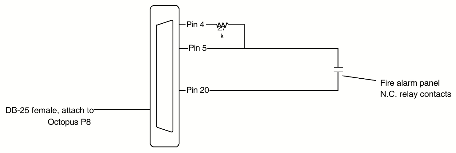
Fire codes in some areas require that the show shuts down if the alarm is triggered. Normally-closed dry contacts from the fire alarm system can be connected to control lines on the Show Computer's P8 serial port, and the alarm being triggered will result in a complete shutdown of the Cyberstar 2000 software if the Alarm=Fire line is set in the config file.


